Electric Vehicle Charging Station from Public Electricity and Solar Panels
Using public electricity and solar panels for the easy and hassle-free charging of Electric Vehicles is an interesting solution to combat the problem of the unavailability of Electric Vehicle Charging Stations.

21 Jun, 2022. 11 minutes read
This article is a part of our University Technology Exposure Program. The program aims to recognize and reward innovation from engineering students and researchers across the globe.
The primary reason why people don't prefer electric vehicles is because of the unavailability of charging stations. Charging stations, unlike petrol bunks, aren't available everywhere. There always exists a fear as to what might happen if the vehicle runs out of battery. People are worried about more straightforward and faster commuting methods in our country rather than saving the Earth from the ill effects caused by pollution.
The project mainly deals with a simple solution to make charging stations more accessible. The solution involves using public electricity and solar panels for the easy and hassle-free charging of Electric Vehicles. This project consists of a scaled-down prototype.
Introduction
A universal charging station charges vehicles of different companies with different batteries with varying charging capabilities, increasing the demand for EVs and ensuring reliability. The easiest way to acknowledge this concept is that the charging mechanism takes to play by simply altering the Current and Voltage to deliver a specific power required by the battery for fast charging. The controllers perform controlled power delivery.
This model is a scaled-down version of the actual, with the systems working exactly. The setup is continuously monitored and made sure it is a foolproof setup with no chances of electricity being stolen. The device is an IOT based programmable, secure interface providing customers with a plugin for charge when in need.11
Solar Energy is a sustainable energy source and is an infinite and clean energy source that is free and eco-friendly. So, it is very efficient & free from environmental pollution. The alarming situation of global warming leads to the full adoption of the renewable energy-based transportation system.
However, their sustainable deployment at a mass level has been a challenging task. To overcome the above predicament, charging electric vehicles using distributed solar energy would be an excellent solution, resulting in net-zero emissions. Solar power would allow us to move to a green initiative swiftly.
The latest technology involving fast charging and better run will result in the increasing usage of electric vehicles. There always lies a hunch in everyone's mind about what might happen if the vehicle runs out of battery. This indirectly leads to choosing a conventional vehicle rather than going pollution-free because the needs are satisfied.
In 2020, India was the fifth-largest auto market, with 3.03 million units sold in the passenger and commercial vehicles categories. It was the seventh-largest manufacturer of commercial vehicles in 2019.

This chart shows how much carbon dioxide is produced in a given year.
• These figures are based on 'production' emissions (i.e., emissions from the burning of fossil fuels within a country's borders).
• These figures look specifically at carbon dioxide emissions – not total greenhouse gas emissions.
• Annual emissions can be primarily influenced by population size – we present the per capita figures above.
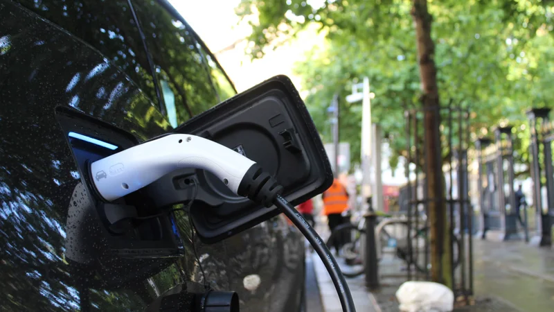
The prototype listed in this report is a portable charging station that is present more frequently and at regular intervals on the roads. This device is placed at the poles of the street lamps, taking power from them and running it through a parallel connection and charging the vehicle plugged in.
The device is an IOT based programmable, secure interface providing customers with a plugin for charge when in need.
Methods And Material
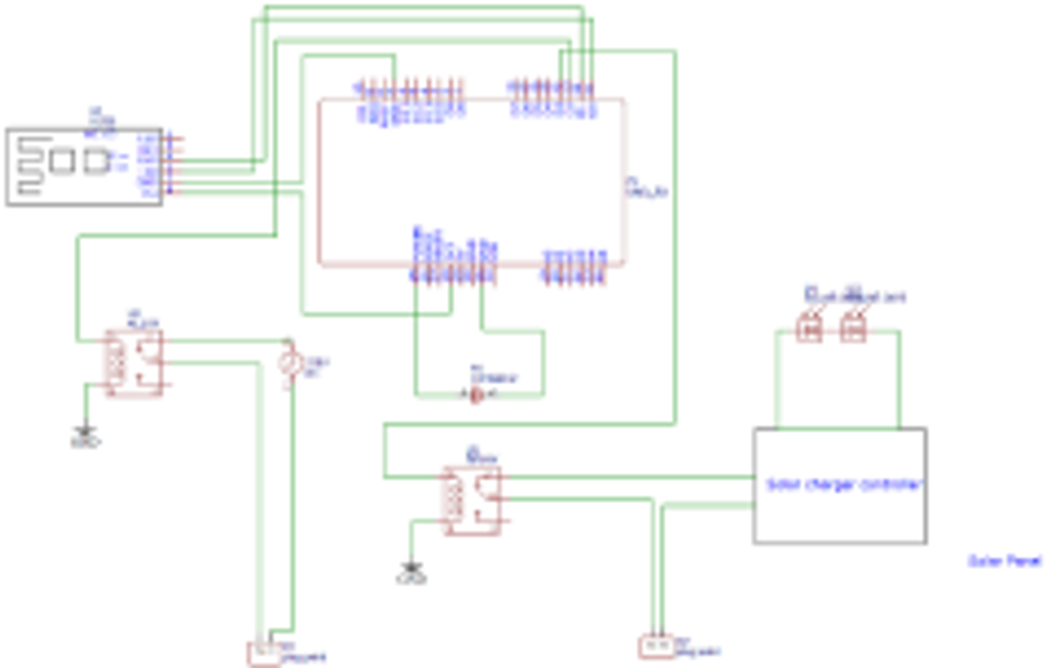
The following components are used in the EVCS set up in a procedural circuit and respective pin diagram. The Arduino, the primary control for the prototype, is explicitly programmed, and it controls the HC05, NEO 6M, and the relay.
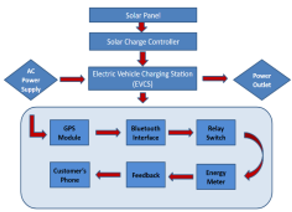
The above figure shows the sequence of steps involved in the working of the EVCS with the respective components. The 2 relays automatically switch between AC Power supply and Solar power.
Arduino Uno
The Arduino Uno is an open-source microcontroller based on the Microchip ATmega328P microcontroller and developed by Arduino. The Arduino board is requipped with digital and analog pins that may be interfaced to various expansion boards (shields) and other circuits. The board has 14 digital I/O pins (six capable of PWM output), 6 analog I/O pins. They are programmable with the Arduino IDE (Integrated Development Environment).
Bluetooth Module (HC05)
Bluetooth SPP (Serial Port Protocol) module is designed for a transparent wireless serial connection setup. The HC-05 Bluetooth Module can be used as a Master or a Slave configuration, making it an excellent solution for wireless communication. This SP Bluetooth module is fully qualified Bluetooth V2.0+EDR (Enhanced Data Rate) 3Mbps Modulation with a complete 2.4GHz radio transceiver and baseband.
Relay
A relay is an electrical device that is operated as a switch. It consists of sets of input terminals and output terminals for single control signals or multiple control signals and sets of an operating contact terminal. The relay switch can have any number of contacts in many contact forms, such as the normally open circuits and the normally closed circuits or combinations of both the circuits. It can easily be turned ON or OFF and let the current go through or not, and the relay can also control it with very low voltages of 5V connected to a battery provided by the Arduino pins.
NEO 6M GPS Module
NEO 6M GPS Module is a Satellite Navigation device that is capable of receiving information from the 24 GNSS satellites that are orbiting around the Earth and then calculating and transmitting the device's geographical position in terms of latitudes and longitudes.
Solar Panel
Solar Panel is a group of photovoltaic cells (PV cells) placed in a framework for the installation. Solar panels renewable energy in the form of sunlight converts it into electricity and then store the electricity in a specified battery, which can then be used to provide electrical loads.
Solar Charge Controller
An n-channel MOSFET that is forward biased is used to stop the current from the battery to the solar panel. A Zener diode (10v) protects from low voltage, which sends positive feedback, turning on the relay. A Zener diode (15v) protects from over-voltage, which sends negative feedback, turning off the relay. Another n-channel MOSFET is used to protect from overcharging the battery by turning off the relay.
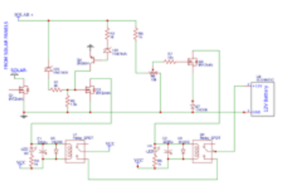
Figure 3: Solar Charge Controller
Digital Energy Meter
The electricity meters operate by continuously measuring the amount of instantaneous voltage and the amount of current and finding the product of these to give the immediate electrical power, which is then integrated against the time to provide the energy used for charging.
Methodology
The GPS module, Bluetooth module, and the relay are all attached to the Arduino in a specific way. The main objective of this model is to obstruct and retract the power flow using a relay with the help of a Bluetooth interface.
The prototype is designed to be placed at the bottom of street lamps. The power lines that flow at the street lamps carry 220v, exactly what is received at our houses. Using this concept, the charging of EVs will take place outside with a voltage of 220v.
Additionally, a solar panel is added, which is used to extract the solar energy and convert it into usable electricity. The panel has its respective solar charge controller, which regulates the voltage flow into the battery. The vehicle which is to be charged has been scaled down and assumed to be a battery of 12v and 10Ah. The solar charge controller extracts the power from the Sun's solar radiation, steps down the voltage, and supplies it to the battery accordingly.
The EVCS contains two relays that switch automatically in delivering power. A light sensor is adapted to detect the presence of sunlight. Relay 1 is turned off in the absence of the Sun, and Relay 2 is active, usable for power delivery.
During the day, in bright sunlight, the user can use either solar energy or conventional electricity from the grid. The 2 Relays which are present can be activated based on the requirement. The EVCS contains an Arduino connected to the GPS module, Relays, and the Bluetooth module. The two possible ways are explained as follows.
Case 1: Solar Charging - Relay 1
In the presence of sunlight, Relay 1 is active and can be turned on or off. The solar radiations are converted into electricity and pass through the solar charge controller. The solar charge controller is a voltage and current regulator to keep batteries from overcharging and overheating. It regulates the current and voltage coming from the solar panels and going to the battery safeguarding it by preventing it from over-voltage, low voltage, and back current. Relay 1 is turned on, and the charge starts to flow from the Solar panel into the battery. At this time, Relay 2 is inactive.
Case 2: Electric grid charging - Relay 2
The electricity from the street pole directly enters Relay 2 (active Relay), and Relay 1 is inactive. The user plugs in his car for charging using the home adapter, and the electricity from the 220v line passes through and charges the vehicle. When the charging sequence begins, it is ensured that the power is supplied from one source only. The responsible relay is the only one that is specifically turned on. Both the relays cannot be on at the same time.
Instance:
An electric vehicle is low on battery; the driver searches for the nearest charging station on his phone. The charging stations are provided with a unique location tag and are located through GPS. The NEO 6M GPS module actively tracks 24-30 satellites and sends the coordinates to the phone. The coordinates are then decrypted, and the exact location is shown on the map.
The vehicle halts at the desired parking space and locates the EVCS. The user can choose between Solar charging (provided the relay is active in the presence of solar radiations) or electric grid charging. The charging wire is plugged into the outlet of the EVCS, or in the case of solar charging, the charging wire is connected to the inlet of the vehicle. The plugged-in socket has a 220v line which has been drawn from the street lamp.
The consumer authenticates as a registered owner of an electric vehicle with the stored database. The credentials are entered, and access is granted. Bluetooth is turned on and an interface is created linked to the respective EVCS, enabling the charge to flow. Engaging and disengaging the power supply is done through the mobile application. Once engaged, the Arduino recognises the user as a trusted source and sends information to the relay. The relay then closes the circuit, providing power flow.
A digital energy meter is placed, and the power consumed is monitored consistently. The consumer's information is recorded and stored in the server, and the number of units consumed along with the per-unit cost is calculated. Once the charging is complete, the circuit is disengaged, and the relay turns off the current flow.
The energy meter tracks the power consumption and stores the data, which is later sent to the consumer's phone. After disengaging the supply or completing the charge, the payment gateway is opened, and the transaction is made.
This completes the entire process of charging an EV. The charging of the EVs is made easy, hassle-free, and
secure. It also ensures that the electricity is not stolen and solely used to charge the respective EVs.
Results and Discussion
Solar Panel- 18V,
Battery- 12V 10Ah,
Power source 220V, 50Hz AC.
Note: The solar charge controller steps down the
voltage from 18V to 12V.
P= Power, V= Voltage, I= Current
P = V*I
P = 12*10
P = 120 Watts
Therefore, the time required to charge from 0 to 80%
is 1 hour. (When 10A is supplied)
Note: Input = 220V AC, the charge adapters have a
nominal output of 12V and 5A.
P = V*I
P = 12*5
P = 60 Watts
Therefore, the time required to charge from 0 to 80% is 2 hours. (5A is supplied) The total Theoretical time calculated to charge from 0 to 100% is approximately 1 hour and 15 mins for solar charging and 2 hours 30 mins for standard charging.
The following experiment of plugging in the EVCS in the single-phase AC power supply was carried outusing a temporary onboard 9V battery that powered the Arduino. Once the power started to flow, the relay, an electrical switch blocked the current to flow out through the output terminal. At present, this is the idle condition of the EVCS. The relay acts as a circuit breaker. When plugged in through the EVCS, any appliance will not work as the current flow is obstructed.
To initiate the mechanism and circuit flow, an android app is used. This app lets you connect to the onward Bluetooth module, which is placed inside the setup. First, a secure and authenticated connection is established between the user and the host. The phone is verified with a stored database which is pre-registered before using the application.
The user Bluetooth and the host Bluetooth are paired, and the relay can be controlled using the various functions present in the application. The user then locates the EVCS switch key inside the application and toggles it ON.
At this moment, the information is received from the phone, and the interaction between the phone and EVCS is set up. The Arduino takes the Bluetooth information, processes it, and then matches it with the ongoing algorithm in the Arduino and sends an output signal to the relay. The relay is then turned on, and the current starts to flow. The whole process of current flow is monitored, and the consumption time is recorded. The plugged-in appliance, which is a battery charger, now receives the current required to charge.
The relay, Bluetooth, and Arduino interface are smooth and secure, and the necessary work is accomplished.
Prototype
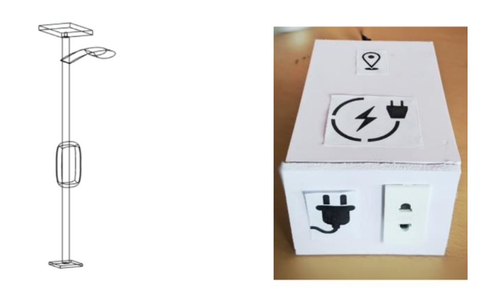
The prototype of the EVCS was made using AutoCAD Software and finally implemented in a working scaled-down model. All the connections and pin configurations with the Arduino and the various components are shown in Figure 6.
Conclusion
The following setup worked effectively and effortlessly with no errors or unwanted functions. The charging of the battery took place, and the time taken with the energy consumption was recorded. There lies no flaws or wastage of electricity as the whole system is monitored throughout the process. Power fluctuations are absent, and the voltage is maintained and regulated with the Integrated circuits and the microprocessor, which play a significant role in ensuring regulated voltage and current flow. This prototype still requires various modifications to make it secure and steal proof. The safety of the battery, the transaction details with specific unit consumption worked without a hitch.
The capability of fast charging with both the sources, solar and 220v power grid energy, must be adapted to shorten the time required for charging. The entire system is a scaled-down model as all the tests carried out were for a small Li-Ion battery of 12V and 10Ah. The charging time was approximately 2 hours 30 mins with adapter and 1 hour 15 mins with solar charging. The device now works with limited sequence and instructions, and delivers power through the switching circuit taken care of by the relay. In conclusion, the switching ON and OFF of the device is secure, and following a set of protocols for the interface between the phone and the EVCS prototype.
References
[1]. Wireless Communication Using HC-05 Bluetooth Module Interface with Arduino, ISSN: 2278 – 7798, International Journal of Science, Engineering and Technology Research (IJSETR) Volume 5, Issue 4, April 2016.
[2]. Development of rapid charging system for EV battery, International Journal of Recent Technology and Engineering (IJRTE), ISSN: 2277-3878, Volume-7, Issue-6S, March 2019.
[3]. Review on Electric Vehicle, Battery Charger, Charging Station and Standards Research Journal of Applied Sciences, Engineering and Technology 7(2): 364-373, 2014 DOI:10.19026/rjaset.7.263 ISSN: 2040-7459; e- ISSN: 2040-7467 © 2014 Maxwell Scientific Publication Corp.
[4]. Real-Time Vehicle Tracking System Using Arduino, GPS, GSM, and Web-Based Technologies, International Journal of Science and Engineering Applications Volume 7–Issue 11,433-436, 2018, ISSN: -2319–7560.
[5]. Real-Time Vehicle Tracking System Using Arduino, GPS, GSM, and Web-Based Technologies, International Journal of Science and Engineering Applications Volume 7–Issue 11,433-436, 2018, ISSN: -2319–7560.
[6]. Electric Vehicles Charging Technology Review and Optimal Size Estimation, Journal of Electrical Engineering & Technology (2020) 15:2539–2552
[7]. Suarez, Camilo & Martinez, Wilmar. (2019). Fast and Ultra-Fast Charging for Battery Electric Vehicles -A Review. 10.1109/ECCE.2019.8912594.
[8]. Design and Implementation of a 12v Automatic Battery Charger
[9]. International Journal of Scientific Engineering and Research (IJSER) ISSN (Online): 2347-3878
About the University Technology Exposure Program 2022
Wevolver, in partnership with Mouser Electronics and Ansys, is excited to announce the launch of the University Technology Exposure Program 2022. The program aims to recognize and reward innovation from engineering students and researchers across the globe. Learn more about the program here.