M-Blocks
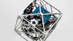
Self-assembling, self-reconfiguring cubic robots that use an internal flywheel and pivoting motions to change their overall geometry. The robots are cubes with no external moving parts. Nonetheless, they’re able to climb over and around one another, leap through the air, roll across the ground, and even move while suspended upside down from metallic surfaces. Inside each M-Block is a flywheel that can reach speeds of 20,000 revolutions per minute; when the flywheel is braked, it imparts its angular momentum to the cube. On each edge of an M-Block, and on every face, are cleverly arranged permanent magnets that allow any two cubes to attach to each other.
MIT
Specifications
| Height | 50 |
| Width | 50 |
| Depth | 50 |
| Actuation Directions | 1 |
| Mass | 143 |
| Total Parts | 178 |
| Actuated Moving Parts | 8 |
| Est. Cost | 250 |
| Maximum Torque | 1.6 |
Overview
The robots are cubes with no external moving parts. Nonetheless, they’re able to climb over and around one another, leap through the air, roll across the ground, and even move while suspended upside down from metallic surfaces.
Inside each M-Block is a flywheel that can reach speeds of 20,000 revolutions per minute; when the flywheel is braked, it imparts its angular momentum to the cube. On each edge of an M-Block, and on every face, are cleverly arranged permanent magnets that allow any two cubes to attach to each other.
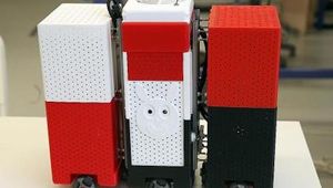
On each edge of a cube are two cylindrical magnets, mounted like rolling pins to compensate for its static instability. When two cubes approach each other, the magnets naturally rotate, so that north poles align with south, and vice versa. Any face of any cube can thus attach to any face of any other.
The cubes’ edges are also beveled, so when two cubes are face to face, there’s a slight gap between their magnets. When one cube begins to flip on top of another, the bevels, and thus the magnets, touch. The connection between the cubes becomes much stronger, anchoring the pivot. On each face of a cube are four more pairs of smaller magnets, arranged symmetrically, which help snap a moving cube into place when it lands on top of another.
As with any modular-robot system, the goal is that the modules can be miniaturized: the ultimate aim of most such research is hordes of swarming microbots that can self-assemble, like the “liquid steel” androids in the movie “Terminator II.” And the simplicity of the cubes’ design makes miniaturization promising. Armies of mobile cubes could temporarily repair bridges or buildings during emergencies, or raise and reconfigure scaffolding for building projects. They could assemble into different types of furniture or heavy equipment as needed. And they could swarm into environments hostile or inaccessible to humans, diagnose problems, and reorganize themselves to provide solutions.
Overall Module Design
The 3D M-Blocks consist of four primary mechanical assemblies: a frame which holds the central assembly which in turn supports the flywheel and the braking mechanism. In addition, the central assembly holds the four batteries which power the module and two of the printed circuit boards (PCBs) which control it.
At the core of the central assembly is a brushless motor and flywheel which, together with the braking mechanism, generate the torques required for all module movements and central assembly plane changes. The entire central assembly is supported by two ball bearings on a diagonal rotational axis which extends through two opposite corners of the cubic rame. As the central actuator rotates about this diagonal axis, the flywheel aligns with each of the module’s coordinate axes.
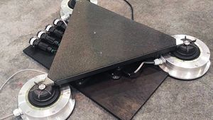
Inertial Actuator Design
The inertial actuator consists of a flywheel and a self-tightening band brake. The flywheel assembly consists of a thin brass ring into which the motor’s rotor is press-fit. This flywheel-rotor assembly is then connected by two bearings, one on either side of the stator, to the surrounding frame such that the flywheel is completely supported and not cantilevered. This allows for the motor and flywheel to have a thin profile while maintaining a stiff attachment to the frame. Once the flywheel is spinning, the 3D M-Blocks use a direct drive electromagnetic coil actuator to activate the brake.
To exert a torque on the 3D M-Block, the motor first accelerates the flywheel to a set speed. With the motor coasting, the module energizes the pancake-shaped coil with 280 turns of #30 AWG wire to create a magnetic field. This magnetic field exerts forces on the two ring magnets and associated keeper, with one of the magnets attracted towards the center of the coil and the other repelled. The resulting force is transferred and magnified by a ratio of two to one by the four-bar linkage to the belt-holder arms. The two belt-holder arms are each attached in a one-way lever configuration to their respective elements in the four-bar linkage, allowing for bi-directional motion, despite the physical constraints of the belt-arms. With one of the belt holder arms pulling on its end of the belt, the mechanism tightens the belt around the flywheel. The other end of the belt is immobilized by a mechanical hard stop.
The current flowing through the coil is always polarized such that the end of the belt which is pulled causes the belt to constrict in the same direction that the motor is spinning. As the belt comes into contact with the flywheel, the friction between the two surfaces causes the belt to self-tighten and completely arrest the flywheel in a matter of milliseconds.
References
Contains an overview of related work that pertain to the system. Presents the mechanical and electrical design of the Modules. Presents data characterizing the hardwar and the results of experiments with the system.
Gives an overview of related work that pertains to the M-Blocks system, and presents the hardware design of the modules. Presents the pivoting cube model and illustrates the types of movements that it supports. Concludes with a short discussion and ideas for future work.
Tags
adaptive morphologymodular roboticssearch and rescueContinue Reading
This comprehensive guide aims to provide engineers with a solid foundation in material handling automation concepts, technologies, and best practices.

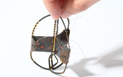
Meet Tribot, the three-legged origami robot designed and built by EPFL scientists. Tri- for three legs and -bot for robot, this super-light critter fits in the palm of your hand, is cheap to build, runs on less than one watt of power, and may one day be deployed in mass for search and rescue mission

1 minute read
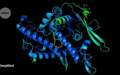
In this episode, we talk about how DeepMind’s AlphaFold algorithm solved protein folding, NASA JPL’s partnership with the Department of Homeland Security to better protect firefighters, and a trial for autonomous shuttles in DTU that can change the transportation infrastructure of the whole country

1 minute read